Dear valued customer:
Welcome to our new website. It will be the new gateway for BOOTS. On top right hand side of the page are your login boxes. Please use your username and password and the site will take you to BOOTS.
Note that we are also updating BOOTS to be compatible with the latest server OS and this will be launched shortly. Thank you for your cooperation.
What Thickness Would be Best?
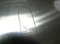
The choice of foil thickness is probably the most important decision in ordering a stencil.
It affects everything from print release to solder joint reliability. Basic rule of thumb is to start with a .007 or .008 foil thickness and adjust thinner as dictated by the smallest aperture to be printed.
Thicker foils will of course be ideal in giving more volume for robust solder fillets especially for larger passives and leaded SOIC's and connectors. But thicker foils cannot be used to reliably print smaller openings. Since the smallest openings must be printable, they are what ultimately determine the foil thickness you choose.

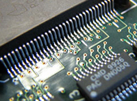
No fine pitch
1.27mm SOIC and passives
0805 and larger.
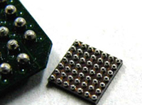
MicroBGA with .010" squares
and 0201 passives.
Here is a quick and easy chart for determining foil thickness.
 |
 |
 |
 |
Choose this |
Leaded Ic's |
BGA's with |
Chips / Passives |
| .007 / .008 | 31 (0.8mm) | 50 (1.27mm) | 0805 |
| .006 | 25 (0.65mm) | 40 (1.0mm) | 0603 |
| .005 | 20 (0.5mm) | 25 (0.65mm) | 0402 |
| .004 | 16 (0.4mm) | 20 (0.5mm) | 0201 |
| 12 (0.3mm) | 16 (0.4mm) | 01005 |
The above chart determines foil thickness based upon the types of parts on the assembly. It is based on our experience and is for recommendation only based on what we believe will yield the best results.
More specific printability formula are provided below. For small rectangular and square openings you will need an area ratio of 0.6, for circles a value of 0.66, and for longer rectangles an aspect ratio of 1.5. The formula changes depending upon the geometry of the stencil opening.
|
|
|

